Skip to main content
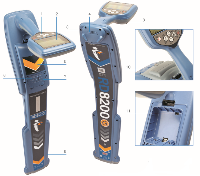
RD7200 Hardware Layout
- Keypad
- LCD with auto backlight
- Haptic (vibration) feedback
- Speaker
- Battery compartment
- Accessory connector
- Headphone connector
- Bluetooth module antenna
- SWING Warning system
- Optional Lithium-Ion battery pack
- USB connector (inside the battery compartment)
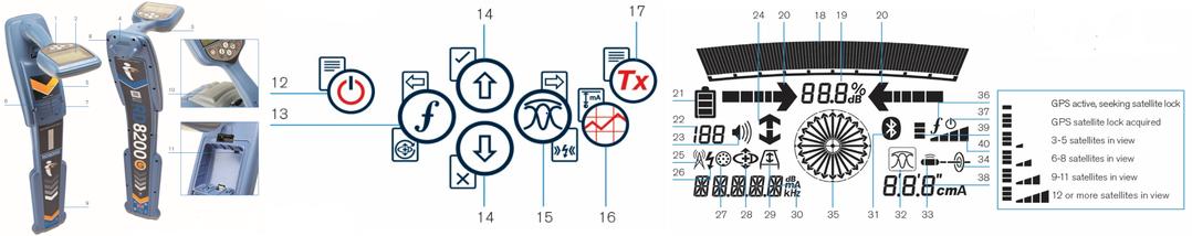
- Power key : Switches the unit on and off. Opens the locator menu
- Frequency key : Selects frequency. Closes sub-menu.
- Up and down arrows : Adjusts the locator signal gain. Scrolls through the menu options.
- Antenna key : toggles Peak, Peak+, Null and Guidance modes. Opens a sub-menu.
- Indicates the signal strength and Peak marker
- Signal strength: Numerical indication of signal strength.
- Null / Proportional Guidance arrows: Indicates the location of the line relative to the locator.
- Battery icon: Indicates the battery level
- Gain readout
- Volume icon: Displays the volume level
- Radio Mode: Indicates when Radio Mode is active.
- Power Mode: Indicates when Power Mode is active.
- Accessory indicator: Indicates when an accessory is connected.
- A-Frame icon: Indicates when the A-Frame is connected.
- Frequency / current / menu readout.
- Antenna mode icon: Indicates antenna selection: Peak, Null, Peak+ and Guidance Mode (model dependent).
- Sonde icon: Indicates that the signal source is from a sonde.
- Line icon: Indicates that the signal source is from a line.
- Compass indicator: Shows the direction of the located cable relative to the locator.
- Transmitter standby indicator.
- Depth readout.